We need to plug in a rather large number of sensors to the UDOO x86 Ultra’s built-in Arduino. During the testing and programming phase, a breadboard worked just fine, but as we move things into the new robot chassis, which is rather tight for space, we need something very compact.
The idea was to create a Arduino shield that plugs onto the board, which then has a number of JTAG plugs, one for each sensor, that routes the wires from the sensors to the relevant Arduino pin.
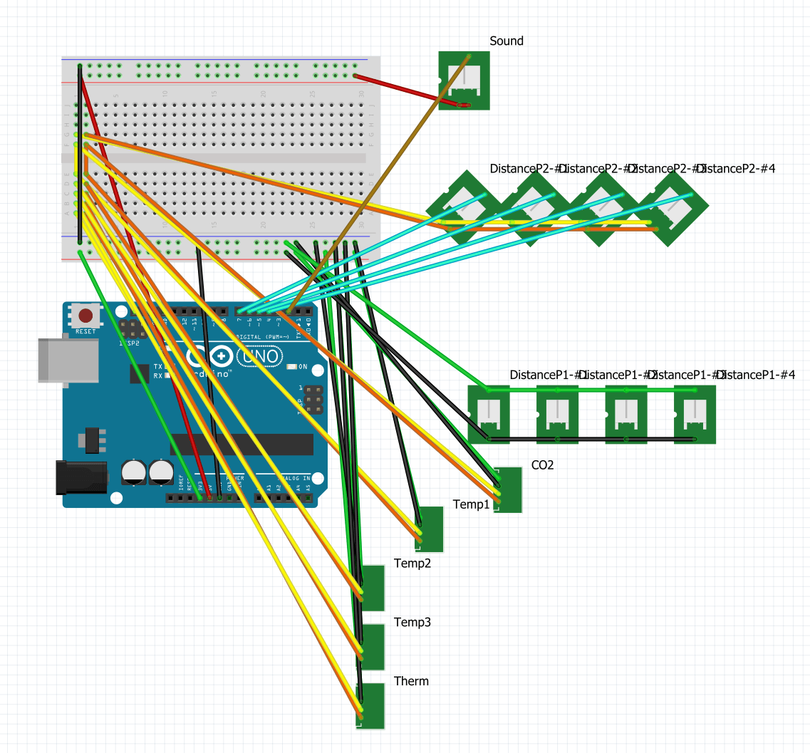
We began designing it in a program called Fritzing.
The first issue we had was that Fritzing does not have 5 pin J-TAG connectors for our five pin sensors. We split it up into three and two pins. Not ideal, but it would have to do. We decided on having the two pin connector be for the power and ground. Once we had the breadboard wired we used the autoroute on the PCB to route all the plugs to the appropriate Arduino pins. The autoroute was awful, in complete honestly, it was a mess. It was impossible to follow anything. We got the thing designed in an hour or two, with the help of Alex, and sent it off to be produced.
Here’s the original PCB with it’s terrible autoroute.
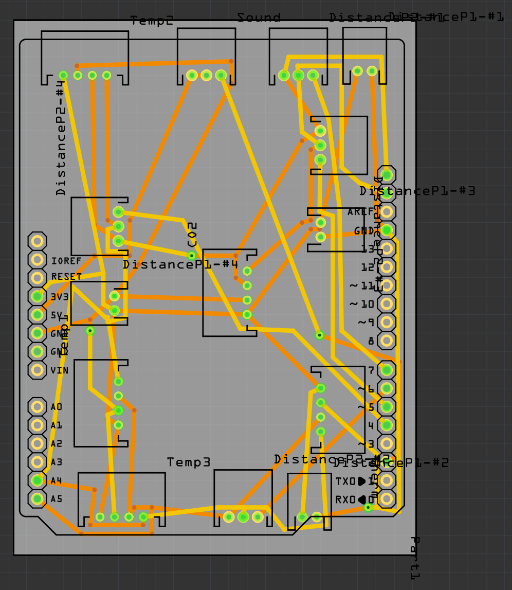
When they arrived, we realised we had a far bigger problem than the bad autorouting. Things were wired wrong, sometimes adjacent pins on the plugs were wired to each other, which should not have happened. Take note of the plug on the PCB in the upper middle and how the first and second pins are bridged. We didn’t notice this at the time. It goes to show, you should really double check these things. We had just assumed the autoroute was messy and not that anything was actually wrong with it.
Fast forward a few days and the PCB boards arrive.
Well, we quickly discovered the aforementioned problems. Also the plugs didn’t fit. The JTAG plugs come in two sizes, 2.0mm and 2.54mm.
We decided we would use Autodesk EAGLE instead. It’s certainly a bit more professional and one of the members of the soccer team knows how to use it if we need a hand.
Our EAGLE schematic ended up looking like this. Rather neat in comparison to Fritzing’s breadboard and schematic.
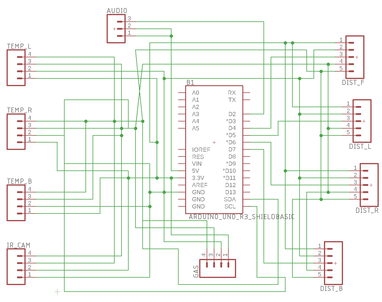
Everything was also labeled far better, with letters indicating the location of each sensor. We had some difficulties while ordering the board. The file wasn’t processed properly and we had no indication that it hadn’t worked until we checked our order several days later, wondering how long it was going to take. Eventually the order was processed.
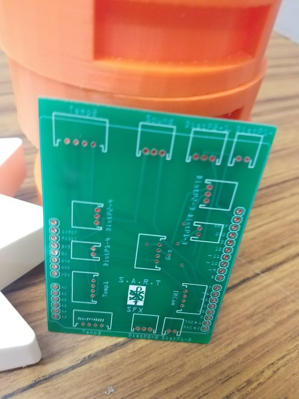
Our PCBs arrived and they look great.
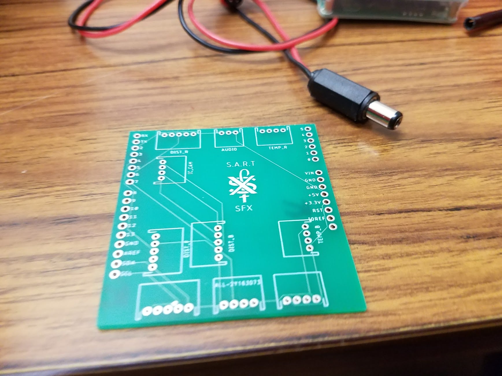
Much better! Cleaner and smaller too! Not perfect though, we must have selected the wrong size JTAG holes because our plugs don’t fit. We’ll just buy different size plugs I think. Easier that way.
Following our philosophy of the S.A.R.T. project being open source, here’s the EAGLE files for our PCB board: